Wing/Closure Rails
|
|
|
|
|
|
|
|
|
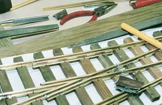
After soldering the stock rails to the six anchor screws, it is time to prepare the wing/closure rails. I always start with the one for the diverging route. It is easier to get the correct curvature when nothing interfers in the space. The other wing/closure rail is straight and little fine adjustment is needed for that one.
|
|
|
To create a sharp bend file a small 90° notch into the base of the rail and clamp the rail in a vise to bend. Use the vise to bend a slight lead-in angle at the frog end of the wing rail
|
|
|
Clean the rail well and spike in place. Double check the position: Proper gauge to stock rail, proper flangeway clearance, proper alignment with frog! Once all of these dimensions are correct, solder rail to anchor screws.
|
|
|
Proceed the same way with the straight route wing/closure rail.
|
|
|
|
|
|
|
|
|
|
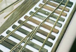
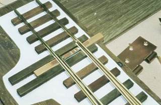
Wing/closure rail of the diverging route soldered and spiked.
|
|
|
|
|
|
Point Rails
|
|
|
|
|
|
|
|
|
The point rails are next. The first turnout I built with hinged point rails, the next one with solid point rails. Solid rail looks better but will require more power to move and keep in position.
|
|
|
The points are shaped by removing the base, part of the web and most of the head of the rail. Mark the length required to clear the stock rail. Clamp the rail in the vise and file. Once you have removed the material on the side that rests against the stock rail you will remove the portion of the head on the opposite side. Round off the tip of the point, to prevent wheels from picking the points. You'll end up with a slender blade which will nestle perfectly into the stock rail.
|
|
|
Once you have the blades prepared you will need to mark the length of the point rails and trim them.
|
|
|
|
|
|
|
|
|
|
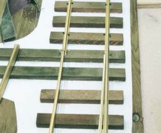
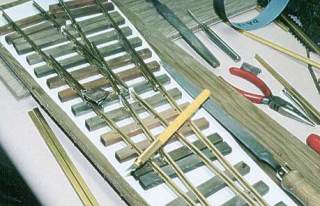
This shows the point of the diverging route.
Note how closely it nestles into the stock rail!
|
|
|
|
|
|
Hinged Points or Solid Points
|
|
|
|
|
|
|
|
|
|
|
Next you'll create the hinge. You need to drill holes into the axis of two anchor screws, the diameter is .052" (#55). Drill .250" deep from the face of the head.
|
|
|
Very carefully mark the position of the pivot point on the tie and then drill the hole for the anchor screw. It has to be precisely centered relative to the wing rail.
|
|
|
Insert the anchor screws to be perfectly even with the top of the tie.
|
|
|
Now position the point rail so that it fits properly into the stock rail. Mark the centre position of the pivot screw on the point rail; drill a 3/64" hole at the marked position into the base of the rail, exactly centered so that it will be in the web of the rail!
Insert a piece of 3/64 brass wire into the hole after you remove some material from the diameter (it should be a slide fit) and solder it. Clean off excess solder to assure the rail sits flat on the anchor screw head. Insert the point rail into the hinge and double check for proper fit. The rail should swivel freely! Two spikes will prevent the rail from lifting out of the hinge. These need to have slight clearance, so as not to restrict the point movement!
|
|
|
|
|
|
|
|
|
|
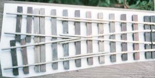
This turnout has hinged point rails.
(Gaps in the rail at right edge of picture)
This will require little force to move the points.
|
|
|
|
|
|
|
|
|
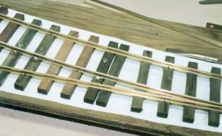
The later version has solid rail from wing rail to points.
This requires more power to move the points but looks much more prototypical.
|
|
|
|
|
|
Guard rails
|
|
|
|
|
|
|
|
|
The profile of the guard rails is basically a piece of rail with part of the rail head removed i.e brought flush with the web of the rail.
|
|
|
Again bend a small lead-in angle on both ends. The base of the rail is snug up against the stock rail and the resultant gap is the desired 2.75mm flange clearance. Spike the guard rail in place and solder the ends to the stock rail.
|
|
|
|
|
|
|
|
|
|
Modified railprofile for the guard rail.
The flange way clearances are 2.75 mm on both the wing- and guard rails.
Larger clearance may be required depending on the Back to Back dimension of the rolling stock.
|
|
|
|
|
|
Throw Bar
|
|
|
|
|
|
|
|
|
|
|
A piece of Printed Circuit Board material is used for the throwbar. Remove a small strip of the copperclad material to insulate the two sides.
|
|
|
Determine the position of the point rails on the throw bar; this will depend on the Back-to-Back clearance of your equipment. Centre the throw bar between the headblock ties. Use two pieces of slightly tapered tie stock to hold the throw bar up against the stock rail, solder the point rail.
|
|
|
In the case of hinged points you will now be able to move the points from side to side; they will stay in position.
|
|
|
The solid rail points will equalize the tension on the throwbar keeping it centered. You will need to apply force and keep it applied to select one or the other position.
|
|
|
|
|
|
|
|
|
|
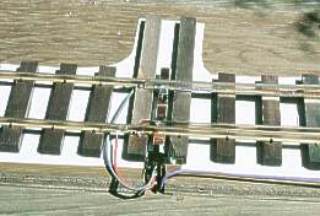
Installed throwbar.
Note the notch at the center of the printed circuit board.
The two pieces of tie stock are used to keep the throwbar up against the stock rail.
|
|
|
|
|
|
Insulating the Frog
|
|
|
|
|
|
|
|
|
The gaps to insulate the powered frog are next. I cut them with a Dremel parting disc.
Make sure you wear eye protection!
|
|
|
I then fill the resulting gaps with a piece of .020" styrene which is cut to the same width as the rail base. Once the strip has been inserted it is secured with industrial strength CA adhesive. Again, follow all the safety precautions.
|
|
|
All turnouts require four gaps to be DCC friendly.
|
|
|
Once the adhesive has set you can trim the styrene to the rail contour.
|
|
|
|
|
|
|
|
|
|
Insulating the frog.
The styrene gets trimmed to the rail contours with a hobby knife.
|
|
|
|
|
|
|
Now all we need to do is wire the turnout. I use a miniature microswitch to power the frog. The switch is actuated by the throwbar.
|
|
|
|
|
|
|
|
In order to make the turnouts DCC friendly the point rails get connected to the adjacent stock rail.
|
|
|
|
|
|
|
|
|
|
Micro switch mounted and wired.
|
|
|
|
|
|
|
|
|
|
|
A comment or two
|
|
|
|
|
|
|
|
|
|
|
As mentioned in the materials and tools list, building your own turnouts requires patience! How long it will take depends on your skills and tools. How well the end result will work however is also a matter of the patience you bring to the job.
|
|
|
If you're in a hurry, you are probably better off buying what you need. Building your own only makes sense if you take the time to build a superior product!
|
|
|
|
|
|
|
|
|
|
|
|
|
|
Previous page
|
|
|
|
|
|
|
|
|
|
|
|
|